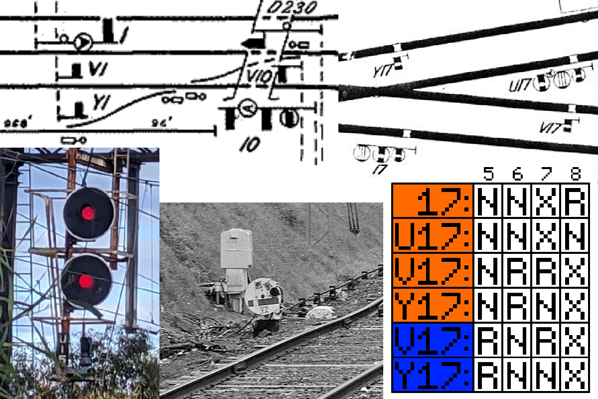
From left to right, then top to bottom: 1973 diagram of Armadale, 1929 diagram of Footscray, home signal U15 at Riversdale, motorised dwarf V2 at Brighton Beach, clearing table of Footscray signals shown above.
From left to right, then top to bottom: 1973 diagram of Armadale, 1929 diagram of Footscray, home signal U15 at Riversdale, motorised dwarf V2 at Brighton Beach, clearing table of Footscray signals shown above.
One of my favourite things about power signalling is that multiple signals could be controlled by one lever. This can save a few levers; the less levers you need, the smaller the frame, and the smaller the frame, the smaller you need to build the signalbox.
*Power signalling is where you have a mechanical lever frame controlling 3 position signals, and all points are motorised as well. Hence "power", all electrically controlled rather than by pull wire or rod.
Power signalling was installed in places that were surrounded by three postion automatic block safeworking. It fell out of favour when relay interlocking and unit lever panel (small electical switches) started to be installed, around the 1950's.
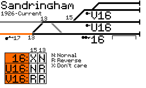
Simplified diagram of Sandringham, showing routes in the up direction. Irrelevant points and signals are not shown.
Here at Sandringham, lever 16 controls signals 16, U16, and V16, but only one of them can go to proceed at a time, depending on what position points 13 and 15 are at. All of these signals take a train to the same point (the up line, towards Melbourne and signal 17). Their criteria for going to proceed, the criteria being the positions of points 13 and 15, is all different, as seen in the bottom left table. Signal 16 doesn't care what position points 15 are at, because a train passing signal 16 doesn't com across those points.
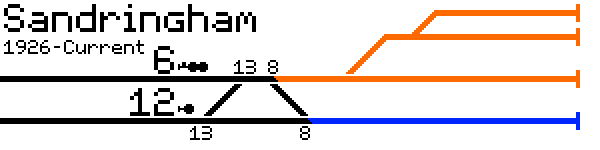
Simplified diagram of Sandringham, showing routes in the down direction. Irrelevant points and signals are not shown.
But what about the other side of Sandringham, signals 6 and 12? Well, there is a permuation of points 13 & 8 (both normal) that allow both signals to clear, which may not be what the signaller wants.
Imagine you want to send a train waiting at signal 12 to the blue track, then right after a train from signal 6 to the blue track. If both signals were controlled by the same lever, then the train at 6 would get a proceed aspect to move towards orange while 12 moves to blue.
Due to this non-conflicting route possibility, we need to put them on seperate levers.
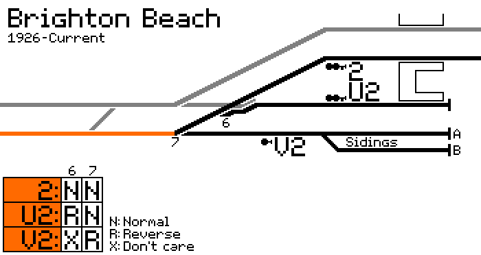
Simplified diagram of Brighton Beach, showing routes in the up direction. Irrelevant points and signals are not shown.
Here's the next example of one destination, multiple signals, just up the line at Brighton Beach. The signal on the mainline gets the main number 2, while the dead end platform gets U2, and then the sidings get V2. Similar to Sandringham, all of these signals have one route from them, and all those routes end in the same place (the up track towards Melbourne, the orange line). Also like Sandringham's 6 & 12, Brighton Beach's 13 & 15 (not shown) cannot use the same lever for the same reason.
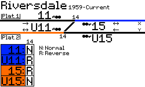
Simplified diagram of Riversdale, showing routes either side of crossover 14. Irrelevant points and signals are not shown.
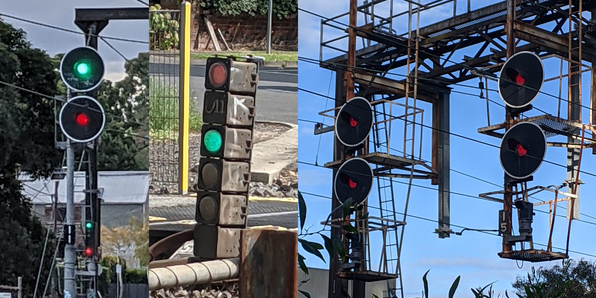
From left to right: Signals 11 (and coactor), small U11 on the ground, then U15 and 15 on the same gantry.
These photos were taken at different times, as 11 and U11 cannot go the proceed at the same time.
Next up is something different, the opposing 11 & U11 and 15 & U15 at Riversdale. The state of crossover 14 determines which signal goes to proceed when you pull either 11 or 15.
You can't have levers 11 and 15 pulled at the same time while 14 is Reverse, but you can while 14 is Normal. Also note that 11 and U15 are normal speed, while U11 and 15 are medium speed (40km/h) over the diverge.
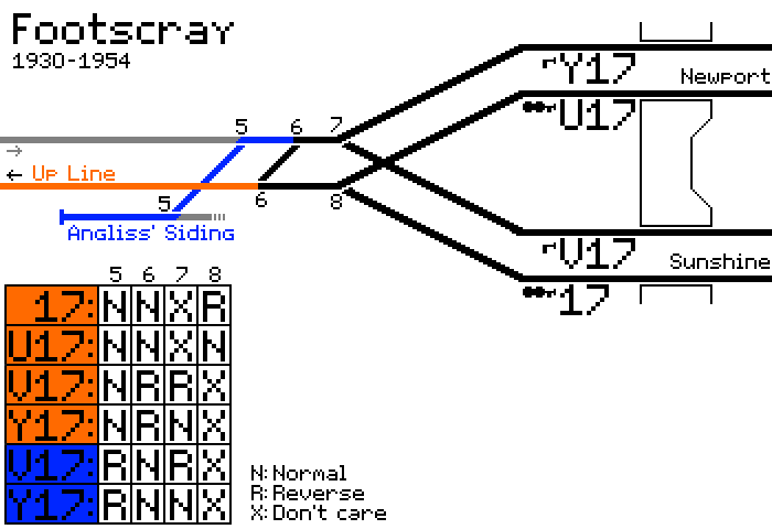
Simplified diagram of Footscray, showing up routes towards Melbourne. Irrelevant points and signals are not shown.
You could've seen it at Footscray, between when power signalling was introduced in 1930 to when the configuartion changed around 1973.
All lever 17 signals (17, U17, V17, and Y17) could be send a train to the Up Line (orange), but as a bonus the setback dwarf signals V17 and Y17 could also send a train to "Angliss' Siding" (blue) via crossover 5.
Hang on though, that's two different end tracks? It seems that reversing points 5 prevents 17 and U17 from going to proceed.
As you can see in the table, all signals and destinations have unique point requirements (normal or reverse), so it still works out that only one signal can go to proceed when lever 17 is pulled reverse.
Footscray also used to have Signals 2/U2/V2 on the up side of the station facing down, and 18/U18/V18 for trains coming in from Newport. View the 1929 signalbox diagram here.
The next question is, why the letters U, V and Y? Why start at U, and why skip W and X? Best guess is to avoid confusion with automatic signal prefixes. Typically, a single letter prefix to a signal indicates it is an Automatic or Repeating signal. A different letter prefix was assigned to each line (seen here, scroll to bottom).
If we started at A, B, C, it would interfere with the designations of the busy Ararat, Sandringham, and Upfield lines. However, letters U and V aren't used anywhere near Melbourne (Mangalore - Tocumwal, and Portland - Ararat). W and X however, are the designations of the Williamstown and Dandenong - Leongatha lines respectively. Power signalling was installed at Footscray and Dandenong in the same year (1929), so maybe the convention to avoid W and X was invented then.
Y is assigned to Bendigo - Yungera, also not near Melbourne, hence 'Y17' at Footscray. Z was never assigned. Do note however that four was the highest number of signals controlled by one lever in this way, but my best guess is Z would have been the next letter used if required.
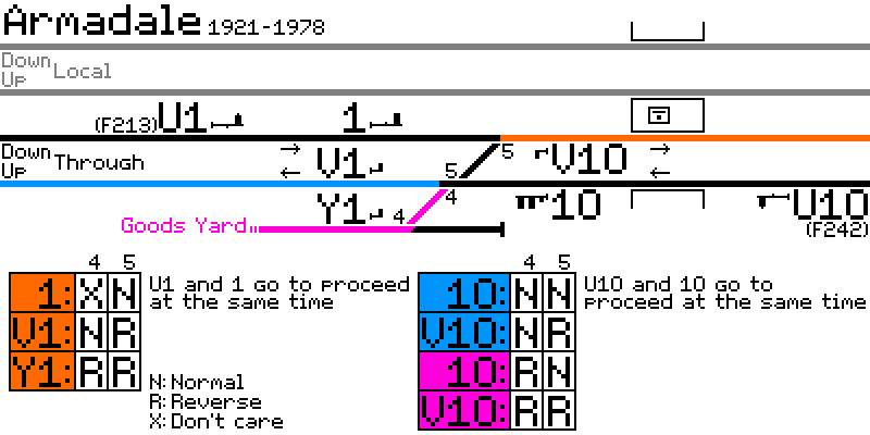
Simplified diagram of Armadale, showing controlled up and down routes. Irrelevant points and signals are not shown.
Armadale had a signalbox solely for controlling movements in and out of the Goods Yard. As seen in this signalbox diagram (and pullchart) from the time, there were only two signal levers used: '1' for all down movements, and '10' for all up movements.
What's different about Armadale are signals U1 and U10, which aren't following that same end route thing we've seen with the above examples. U1 and U10 were provided to give extra protection for when the crossovers, 4 and 5, were reversed. There would be two signals at stop before you reached the points for trains going along the mainline.
Signals 1 and 10 were fitted with a red 'A' (automatic) indicator, so the signalbox could be switched out and be able to send mainline trains through automatically without a signaller present.
If you're wondering out the short section of straight track past Y1, and if it would've gone to proceed if 4 is normal, I don't think so. The track was probably just there in the event of any runaway rollingstock from the goods yard to derail away from the mainline.
The connection the the goods yard was removed in 1978, with the crossovers abolished, signals 1 & 10 getting converted to automatic signals, and the dwarf signals removed.
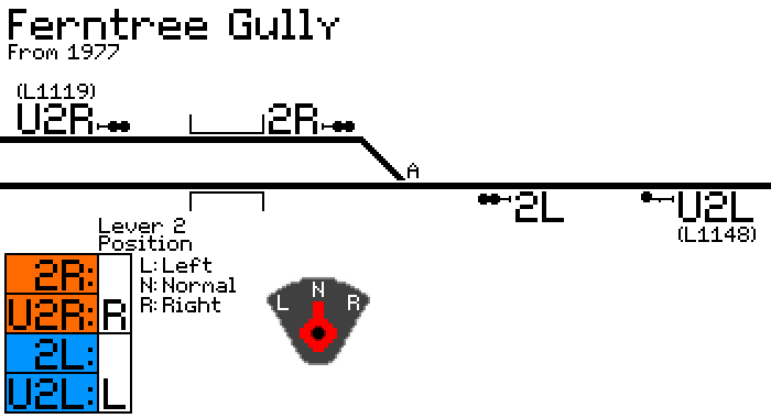
Simplified diagram of Ferntree Gully, showing all controlled signals and points. A drawing of the signal lever is also shown. Irrelevant signals are not shown.
We are diverging a bit and looking at something different: Signals U2R, 2R, 2L, and U2R as well as points A at Ferntree Gully, all of which are controlled by one three-position electrical switch, from the Upper Ferntree Gully panel (picture, far left). As further explained here, putting the lever in the left position, points A move to the normal position and signals 2L and U2L clear. Putting the lever in the right position moves points A to reverse, and clears signals 2R and U2R. Leaving the switch normal will keep all signals at stop. Similar double line to single line with #L and #R signal setups were at East Malvern, Mount Waverley, Syndal, and Glen Waverley (seen here), during the Glen Waverley line's CTC days (1958-1964). Signals U2R and U2L are similar to the U1/U10 signals at Armadale, just giving an extra length of protection to the points. A down train would be stopped at U2R (L1119) while an up train is still leaving the single line section.
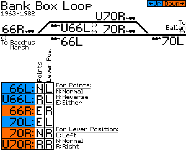
Simplified diagram of Bank Box Loop, showing the signals.
Last up: Bank Box Loop ('73 diagram here), with it's signals 66R, 66L, and U66L on the up end, and 70R, U70R, and 70L on the down end. Regrettably, I don't know the designations for the points. It is also becoming more apparent that the convention is 'L' for the up direction, and 'R' for the down direction, corresponding to the direction you would be moving the switch next to a lit diagram.
We are now back to 'U' signals being the alternate start point for a route with the same end point, either U66L or 66L to the up single line, or 70R or U70R to the down single line.
It seems there would have been 4 levers for this location (which was controlled from a panel inside Bacchus Marsh signalbox), 3 position levers 66 and 70, and two point levers (or possibly these were push buttons).
The signaller would place the lever 66 or 70 in the left or right position, then depending on the position of the points and signal lever position, one of the three signals would go to proceed.
Either that, or there were only two levers (66 & 70), which would've set the points to the empty track, and then set the loop-bound signal to proceed, then after changing the other lever, would send the train out the other side.
In 1982, the loop was extended, the signals were renumbered to all have different numbers, and the control panel was modified ('82 diagram, and photo of panel).
Original Twitter thread by me
Signalling Record Society Victoria for all of your signalling record needs. I refered to many archived diagrams for this posts.
VicSig, for compiled location information and changes over the years among other things.
vrhistoy.com Victorian Station Histories page for detailed changes and diagrams for many locations.
victorianrailways.net
Thanks to David Stosser for making me aware of Armadale's power signalling, as well as providing other relevant information.